
Spark Logic

RTC Libs.

ahull Mon May 18, 2015 7:16 pm

One of the things that I would like to get working is the RTC on the STM32F103XXX – We briefly touched on this before.

Most boards have a 32,767 Hz oscillator or crystal on them and therefore only need a battery/battery holder (possibly with an in-line schottky diode, put probably not) to allow us to get the RTC operational.

What I have discovered so far.

1) There is some sort of attempt to get this working in ./hardware/Arduino_STM32/STM32F1/libraries/Untested/RTClock/
This is incomplete and incompatible with the current versions of rcc.c and rcc.h

There is a “new” version of the rcc libraries in ./hardware/Arduino_STM32/STM32F1/libraries/Untested/RTClock/new RCC/
This is not compatible with the current rcc libraries either.

2) I am unclear which rcc.[h,c] I need to try to merge or adapt the changes form “new RCC” to as there seem to be a number of candidates.

./hardware/Arduino_STM32/STM32F3/cores/maple/libmaple/stm32f3/include/series/rcc.h
./hardware/Arduino_STM32/STM32F3/cores/maple/libmaple/stm32f3/f3_rcc.c

./hardware/Arduino_STM32/STM32F3/cores/maple/libmaple/include/libmaple/rcc.h
./hardware/Arduino_STM32/STM32F3/cores/maple/libmaple/rcc.c

./hardware/Arduino_STM32/STM32F1/libraries/Untested/RTClock/new RCC/rcc.h.new
./hardware/Arduino_STM32/STM32F1/libraries/Untested/RTClock/new RCC/rcc.c.new
./hardware/Arduino_STM32/STM32F1/libraries/RTClock/new RCC/rcc.h.new
./hardware/Arduino_STM32/STM32F1/libraries/RTClock/new RCC/rcc.c.new

./hardware/Arduino_STM32/STM32F1/cores/maple/libmaple/rcc.c
./hardware/Arduino_STM32/STM32F1/system/libmaple/stm32f2/include/series/rcc.h
./hardware/Arduino_STM32/STM32F1/system/libmaple/include/libmaple/rcc.h
./hardware/Arduino_STM32/STM32F1/system/libmaple/stm32f1/include/series/rcc.h

./hardware/Arduino_STM32/STM32F4/cores/maple/libmaple/rcc.c
./hardware/Arduino_STM32/STM32F4/cores/maple/libmaple/rcc.h

Replies

ahull Sun May 24, 2015 9:21 pm

Just in case you are wondering, that little CR1220 should last 2 to 3 years with the system powered off.

If we assume the typical current consumption which the STM32F103 datasheet (page 45) states to be around 1.5uA at between 25 – 60 C – and the typical capacity of a CR1220 cell is between 38mAh to 40mAh

Therefore our CR1220 cell should run (worst case) for 25333.333333333 hrs which is 1055.45 days, or 2.89 years. The battery should only drain if the equipment is not being powered so it should last longer if the equipment gets more usage.

However the cell will also self discharge to some minor extent (around 1% per year), which will shorten its life very slightly.

We are also draining such a tiny current that the cell capacity will effectively be greater (i.e. it should last longer).

Allowing for these factors, the above is a reasonable estimate.

RogerClark Sun May 24, 2015 10:49 pm

OK

My RCT board comes with a button cell, but I’ve no idea if its flat or not.

I’ll need to fire up the board this evening and test the new code.

ahull Sun May 24, 2015 11:05 pm

RogerClark wrote:OK

My RCT board comes with a button cell, but I’ve no idea if its flat or not.

I’ll need to fire up the board this evening and test the new code.

RogerClark Mon May 25, 2015 4:47 am

Andrew

You are right, Its soldered onto the bottom of the board, so is likely to be a NiCad button cell, so is probably charged via a simple resistor circuit

I will need to load the generic bootloader onto that board and give everything a try when I get chance

ahull Mon May 25, 2015 11:22 am

Quick word of warning. If you do decide to add a battery, check that the VBATT pin on your board is not already wired to 3.3V, if it is…. BANG!

See here for the results of *not* checking first :oops:

If VBATT is at 3.3V you will need to put a schottky diode or some other protection depending on your battery type in series with the battery to protect it from inadvertent charging (i.e. exploding).

ahull Mon May 25, 2015 1:11 pm

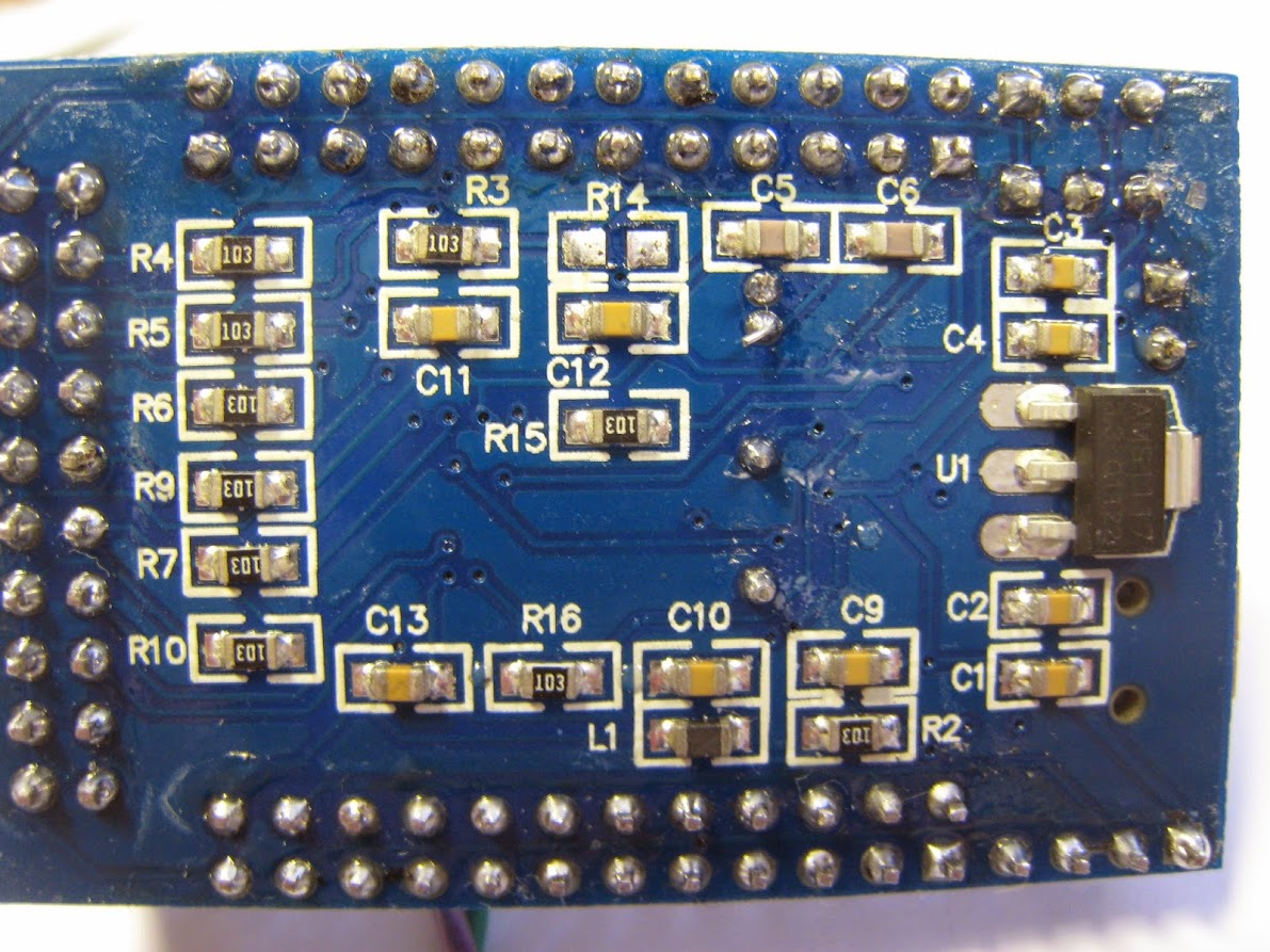
The fix on the case of the board I was using was to remove R14 from the board, as this was shorting the VBAT pin to the 3v3 supply.

Image

With the zero ohm resistor removed, no smoke, no loud noises and the RTC works as expected. Now what the logic of shorting that pin high was I have no idea. Possibly the original schematic called for a diode, but zero ohm links are cheaper… I would suggest a jumper rather than a link would have been a smarter call.

victor_pv Mon May 25, 2015 2:14 pm

From the datasheet I understand the MCU has an internal switch to provide power to the RTC from VCC when there is power in it, so I think nothing should connect vBAT to vcc for proper operation, not even a diode.
On another note, I understood in a post Andy wanted to get milliseconds from the RTC, I think that is possible by reading the current preescaler value, in registers RTC_DIVH / RTC_DIVL and dividing by the appropriate number. Page 481 of the datasheet, although as Roger pointed we already have other sources of milliseconds.
If the time library in arduino provides for a way to get milliseconds from it, then those registers could be used to get them here.

ahull Mon May 25, 2015 5:42 pm

victor_pv wrote:From the datasheet I understand the MCU has an internal switch to provide power to the RTC from VCC when there is power in it, so I think nothing should connect vBAT to vcc for proper operation, not even a diode.

RogerClark Tue May 26, 2015 11:15 am

Andy,

Can you give this code a try on your battery backed system ;-)

#include "RTClock.h"

#define BKP_REG_BASE (uint32_t *)(0x40006C00 +0x04)

static inline int readBKP(int registerNumber)
{
if (register>9)
{
register+=5;// skip over BKP_RTCCR,BKP_CR,BKP_CSR and 2 x Reserved registers
}
return *(BKP_REG_BASE+registerNumber)&0xffff;
}

static inline void writeBKP(int registerNumber,int value)
{
if (register>9)
{
register+=5;// skip over BKP_RTCCR,BKP_CR,BKP_CSR and 2 x Reserved registers
}

*(BKP_REG_BASE+registerNumber)=value&0xffff;
}

//#define TEST_WRITE
#define REG1 0
#define REG2 1
void setup()
{

Serial.begin(115200);
rtc_init(RTCSEL_LSI);

#ifdef TEST_WRITE
writeBKP(REG1,0x1234);
writeBKP(REG2,0x5678);
#endif

}

void loop() {

Serial.print("reg 1 ");Serial.println(readBKP(REG1),HEX);
Serial.print("reg 2 ");Serial.println(readBKP(REG2),HEX);
delay(1000);
}

ahull Tue May 26, 2015 11:45 am

Nice.. I’ll give that a try on the “ugly board”.

ahull Tue May 26, 2015 12:18 pm

Yup, that works.

I fixed an error where you had referred to register at one stage, and registerNumber at another, and I modified to allow me to use usb serial.

#include "RTClock.h"

#define BKP_REG_BASE (uint32_t *)(0x40006C00 +0x04)

// Create USB serial port
USBSerial serial_debug;

static inline int readBKP(int registerNumber)
{
if (registerNumber > 9)
{
registerNumber += 5; // skip over BKP_RTCCR,BKP_CR,BKP_CSR and 2 x Reserved registers
}
return *(BKP_REG_BASE + registerNumber) & 0xffff;
}

static inline void writeBKP(int registerNumber, int value)
{
if (registerNumber > 9)
{
registerNumber += 5; // skip over BKP_RTCCR,BKP_CR,BKP_CSR and 2 x Reserved registers
}

*(BKP_REG_BASE + registerNumber) = value & 0xffff;
}

// #define TEST_WRITE
#define REG1 0
#define REG2 1
void setup()
{
serial_debug.begin();
//Serial.begin(115200);
rtc_init(RTCSEL_LSI);

#ifdef TEST_WRITE
writeBKP(REG1, 0x1234);
writeBKP(REG2, 0x5678);
#endif

}

void loop() {

serial_debug.print("reg 1 "); Serial.println(readBKP(REG1), HEX);
serial_debug.print("reg 2 "); Serial.println(readBKP(REG2), HEX);
delay(1000);
}

mrburnette Tue May 26, 2015 12:54 pm


.. so it works, the data survives the power being removed :D

My understanding is that these registers are cmos ram, I presume they are zero wait state, so they have all the advantages of ram and none of the disadvantages of flash.

That is my understanding, too. The silicon is laid out with different power domains, so the back-up battery powers the RTC domain and these registers are in that power domain.

Ray

ahull Tue May 26, 2015 3:55 pm

I had to try the obvious experiment, based on the fact that the STM32F103C8 and CB appear to have the same flash, I checked to see if the C8 actually has more registers.. it seems not. :( However I can read and write to all ten 16 bit registers (20 bytes) that the datasheet states are present.

Below it the result of writing 1234 5678 c5c5 5c5c 1235 5678 etc.. to the first 16 possible registers… as you can see 16 bit registers 1 to 10 work perfectly.

...
reg 1 1234
reg 2 5678
reg 3 C5C5
reg 4 5C5C
reg 5 1234
reg 6 5678
reg 7 C5C5
reg 8 5C5C
reg 9 1234
reg 10 5678
reg 11 0
reg 12 0
reg 13 0
reg 14 0
reg 15 0
reg 16 0
reg 1 1234
reg 2 5678
reg 3 C5C5
reg 4 5C5C
reg 5 1234
reg 6 5678
reg 7 C5C5
reg 8 5C5C
reg 9 1234
reg 10 5678
reg 11 0
reg 12 0
reg 13 0
reg 14 0
reg 15 0
reg 16 0
...

RogerClark Tue May 26, 2015 11:06 pm

Thanks Andy

I did test that it survives a reset, which is handy in its own right.

LOL.

While I was looking at where we should put these functions, I found that there are already functions for them in the core code

bkp_f1.c

#include <libmaple/bkp.h>

void setup() {
// put your setup code here, to run once:
Serial.begin(115200);
bkp_init();
bkp_enable_writes();
//bkp_write(1,0x1234);
}

void loop() {
// put your main code here, to run repeatedly:
Serial.println(bkp_read(1),HEX);
delay(500);
}

ahull Tue May 26, 2015 11:12 pm

Roger I presume that bkp_read(x) only allows valid “registers” to be read. Does it throw an error if you specify bkp_read(99) or indeed bkp_read(11) on an STM32F103C8 or will bkup_read/write effectively let you peek/poke random values wherever you want?

RogerClark Tue May 26, 2015 11:25 pm

Andy,

It has ASSERTS in the code, but they don’t do anything except if DEBUG is turned on at e.g. in platform.txt

uint16 bkp_read(uint8 reg) {
__io uint32* dr = data_register(reg);
if (!dr) {
ASSERT(0); /* nonexistent register */
return 0;
}
return (uint16)*dr;
}

mrburnette Wed May 27, 2015 12:00 am

I’m not sure if there is a reason, we don’t just run bkp_init() in the startup code.
I can see the advantage of not always calling write_enable() but apart from always making the code a tiny bit bigger
As This is a core feature that all ST32’s have.

As your intent is to utilize the high register for the bootloader, that register must be masked from user write access anyway. I would go ahead and rewrite the function, mask the write to [9] for the F103 ([41] for high density) and set the error return to -1. Including in the startup code seems reasonable.

Ray

RogerClark Wed May 27, 2015 12:16 am

Ray,

I think it will be easier to mask off the first register, so that when the API accesses register 1 its actually register 2, otherwise the code that has to skip the 5 control reg’s between the 2 blocks of bkp reg’s could be a bit confusing.

I’m not sure if the loss of one 16 bit reg for the bootloader is a big issue. But it would make the bootloader more flexible. In fact, we could treat this one “reserverd” register as some sort of special storage, as the bootloader would only need one or two bits of the 16 bits.

Also…
Leaflabs have coded this with register numbers starting at 1, which is in line with the hardware names, but I’m not entirely sure I like numbering from 1, makes sense.

Perhaps I should change the code so that we mask off first reg for use with the bootloader and then use “BKP_REG2” as register ( 0 ) in the code

Or, do you think that would be really confusing?

I think that definitely, initialising this as part of the normal RCC stuff, would not be a big overhead.

And I could always call bkp_write_enable when you do a write in the code. i.e to save having to remember to add that line.

After all, these functions are unlikely to be used for anything that is time critical, so having write take a bit longer is unlikely to cause any issues.

Looking at the real HAL names for this,

It would probably be better to change them to the STM standard

BKP_WriteBackupRegister(BKP_DR1, FirstBackupData);

and

BKP_ReadBackupRegister(BKP_DR1)

and do some defines for the BKP_DR’s

mrburnette Wed May 27, 2015 12:33 am

Or, do you think that would be really confusing?

If the read/write routine reserves [0] for both medium & high density devices devices, I see no confusion. In fact, maybe mask off a byte for the bootloader and a byte for the user … uint8_t

So, user code can write to [0] but only as a byte. [1] … [9] on medium density and [1] … [41] on high density are user available.

I’m just rambling as I only see this area needed for run-time state preservation while the uC is powered on.

Ray

hyperion Thu Mar 22, 2018 4:44 pm

hi. I try calibrate RTC by this method.
Cant found english manual for this. Only in Russian
http://spec-project.ucoz.ru/index/kalib … m32f1/0-14
to calibrate i need record bit 1 to BKP_RTCCR_CCO backup register.
example BKP->RTCCR |= BKP_RTCCR_CCO;

i correctly understand command will be

bkp_init();
bkp_enable_writes();
bkp_write(BKP_RTCCR_CCO, 0x1);

i try read after this
for (uint8_t iii=0; iii<20; iii++){
Serial.print(bkp_read(iii),HEX);
Serial.print(” “);
}
and read only zeros.

what i doing wrong?

Sign in to reply