
Spark Logic

$10 O-Scope revisited

ahull Sat May 09, 2015 12:56 pm

Over the last few days I’ve been playing with Ray’s STM32 Oscilloscope idea.

Image

Some preliminary results are available here..

https://github.com/pingumacpenguin/STM3 … ontruction

My take on the Scope Sketch is here..

https://github.com/pingumacpenguin/STM32-O-Scope

Its a fun little project and well worth building just for the entertainment value. Currently bandwidth is a little limited, but with a little extra effort it would be possible to make a fully functional 2MHz Scope for next to nothing. Ideal for probing i2c, audio and other low speed signals.

EDIT: We managed to squeeze the maximum speed out of the ADC, read further through the thread for details. The github code includes all of the enhancements made of the course of this thread.
Replies

victor_pv Sun May 24, 2015 11:02 pm

Nice, I need to try it out with the RTC.

I cleaned up the code for the libraries a bit more, so they don’t print artifacts if the sketch tries to draw a line out of range.
You will see that as some stray green dots depending on the input wave, specially with noise (just putting my finger on it).

You can download the latest version from here:
https://github.com/victorpv/Arduino_STM … LI9341_STM

I sent a pull to Roger, so it should be updated in his repo soon, as the previous one does not compile anymore after the SPI library has been updated.

mrburnette Mon May 25, 2015 2:39 am

The neatest part of this is that you are using Pix of the O’scope in operation to show capability and issues.

Job well done… this should be a required build for any serious tinkerer who does not have access to a scope. This would be a great PSoC 4200 project due to the “free” analog subsystem and analog mux + OpAmp. FYI, only $4 http://www.cypress.com/?rID=92146
( do not even consider 4100 )

Ray

ahull Mon May 25, 2015 2:47 pm

Ray, that looks like a pretty interesting part. I may have to have a play with one of those.

ahull Mon May 25, 2015 2:50 pm

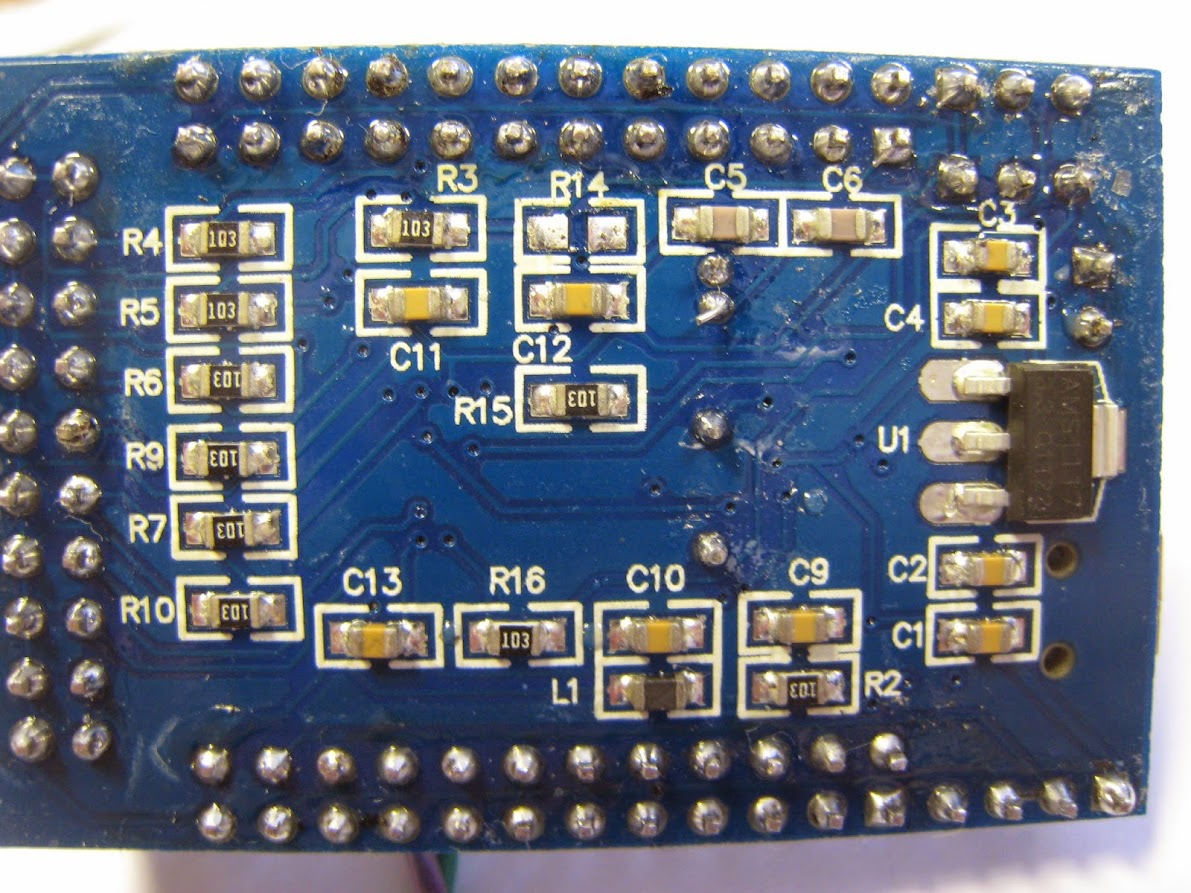
For what it is worth I flashed the code to my “ugly board” (below) to compare.

Image

The following picture is the output from this “scope”, with PB0 jumpered to PB1 (i.e. test out to analog in with no test probe). I promise I haven’t faked this… it looks like the squarest square wave I have ever seen.

Image

So with a little work on the probe, we should get some pretty clean results, so long as we can keep the interference and reflections down.

mrburnette Mon May 25, 2015 3:04 pm

I promise I haven’t faked this… it looks like the squarest square wave I have ever seen.

Hehehehe…. and all for under $10. Very nice. (Pig carcass extra, batteries not included!)

Ray

FlyingScope.jpg
FlyingScope.jpg (12.7 KiB) Viewed 2453 times

mrburnette Mon May 25, 2015 3:07 pm

ahull wrote:Ray, that looks like a pretty interesting part. I may have to have a play with one of those.

Rick Kimball Mon May 25, 2015 4:06 pm

How do you have time for the STM32 stuff if you like those?

ahull Mon May 25, 2015 5:02 pm

mrburnette wrote: I promise I haven’t faked this… it looks like the squarest square wave I have ever seen.

victor_pv Mon May 25, 2015 5:34 pm

ahull wrote:For what it is worth I flashed the code to my “ugly board” (below) to compare.

Image

The following picture is the output from this “scope”, with PB0 jumpered to PB1 (i.e. test out to analog in with no test probe). I promise I haven’t faked this… it looks like the squarest square wave I have ever seen.

Image

So with a little work on the probe, we should get some pretty clean results, so long as we can keep the interference and reflections down.

ahull Mon May 25, 2015 7:03 pm

Yes, that is using both ADCs – there is some difference in the readings, they haven’t simply flat lined at 0V and 3V3 a I suspected, here is a close up view of some of the data.

Image

As you can see the two ADCs agree within a very close margin in this sample, 8 parts in 4096 or around 0.195% which if it is typical is pretty impressive.
EDIT: To put that in context, for our 3.3V signal we are measuring to something around +/- 0.0064 V or 6.5mV. all this without any additional amplifier or buffer. Not quite good enough for an EEG which requires around 0.5uV resolution perhaps, but still very useful precision.

victor_pv Tue May 26, 2015 12:43 am

I specially like that there are a few samples in a row with the exact same value, meaning both ADCs read the same for at least a couple of samples in a row. Perhaps most of the noise that is left is just from the board and voltage regulation more than from a variance in the ADCs. Still I think that level of noise is something I can live with.

I had separated the ADC setup code from the takeSample routine, but did not push that up, and was before you added the RTC code.
I will try to download your latest, take the ADC setup to a new routine again, and then push right away before you add some new feature ;)

I was thinking on turning this into a CoOS or FreeRTOS sketch, mostly for demonstration purposes on what the RTOS can do, and get more experience with them. I think CoOS results in a really small Flash and RAM footprint and makes coordinating tasks pretty easy, but not sure the PigScope will benefit from it. Were you thinking on adding any new functionality to it that could benefit from an RTOS?

BTW, the ugly board makes a great low noise oscilloscope if nothing else…

Docedison Tue May 26, 2015 6:16 am

All I’ve seen here in this thread is brilliant hard work…
But a voltage follower might be of use here..
I see from the wave forms the effects of a two sided PCB and the combination of an impedance mismatch between the probe and the ADC input..
A ‘Fast’ voltage follower used as an interface between the ADC input and the probe would go a long way to relieve ?some of the very obvious lack of high frequency response or the rounded leading edges of both the inputs..
I repaired all the test equipment on my last job (retired in 2008) and O’Scopes were my ‘other’ right hand..
What I see is a mismatch on the ADC input. By driving the input with a unity gain buffer or a fast Op-Amp would IMO help a great deal..
As the output impedance of a buffer or voltage follower is typically under 100 ohms and the input impedance is limited by the sampling rate of the ADC.
Just my $.02 worth..
It’s nice that there is a separate forum for this most amazing/bang for the buck board(s)…

Doc

ahull Tue May 26, 2015 9:57 am

Victor, I don’t intend to add anything more at the moment. My next target is to make displaying the waveform clearer. The code as it currently stands is a little untidy, so I might clean things up a bit too. But that can all wait till you have merged your changes.

ahull Tue May 26, 2015 10:09 am

Doc, a voltage follower or some kind of buffer would be a very good idea. The scope started life as a bit of a what if… so I was trying to see how far we could push things with little or no additional components.

It may be possible to passively trim the scope probe to match the impedence of the ADC and eliminate the high frequency issues, perhaps taking an attenuation hit to improve high frequency response. I haven’t done anything about this yet, so any input would be welcome.

An Active Probe approach may be the only option though, but that adds a layer of complexity and cost. I wonder what the simplest and cheapest way of doing this would be, given our low cost low bill of materials goal. An active probe would also allow us to add some level of input protection, but as I said in a previous post, blowing up the uC and/or ADC would be sad, but they only cost a couple of quid, so not the end of the world. Input protection could simply be a couple of zenners and a picofuse or a mob. but again I hadn’t given this much thought. Any protection across the input is likely to have knock on effects on the frequency response, particularly in light of the lack of buffering.

Off topic I know Doc,but you don’t know where I might find parts for an old Metrix OX 2000 scope do you. I have the carcase of one in my garage, it looks like a long term project, since it is missing the PSU, analog input card and CRT driver board. A saner individual than me would no doubt just put it in the bin. :D

mrburnette Tue May 26, 2015 11:59 am

Rick Kimball wrote:How do you have time for the STM32 stuff if you like those?

victor_pv Tue May 26, 2015 2:57 pm

Andy I’ll download your latest version later and separate the ADC setup from the capture and push an update.
After that I’ll try to adapt it to CoOS, but I’ll keep the function names, so if you make changes within a function before I push that up, all we need to do is copy that function straight up.

ahull Tue May 26, 2015 3:24 pm

victor_pv wrote:Andy I’ll download your latest version later and separate the ADC setup from the capture and push an update.
After that I’ll try to adapt it to CoOS, but I’ll keep the function names, so if you make changes within a function before I push that up, all we need to do is copy that function straight up.

victor_pv Wed May 27, 2015 12:42 am

I was trying to compile the latest version, that includes the RTC part, and I get errors indicating that gmtime and mktime are not declared in this scope:
‘gmtime’ was not declared in this scope

I don’t see either one of those in Paul’s time library, where should they come from?

RogerClark Wed May 27, 2015 12:51 am

#include <time.h>
void setup() {
// put your setup code here, to run once:

const time_t* t;
gmtime(t);
}

victor_pv Wed May 27, 2015 1:39 am

RogerClark wrote:#include <time.h>
void setup() {
// put your setup code here, to run once:

const time_t* t;
gmtime(t);
}

Sign in to reply