Spark Logic

DLO-138 OScope

willfly1 Sun Feb 26, 2017 5:38 pm

DSO-138 Oscope firmware

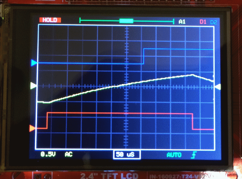
DLO-138 is alternate firmware for DSO-138 and adds second analog channel, two logic channels, more sample depth and serial port data output.

Code: https://github.com/ardyesp/DLO-138

pic3.png
pic3.png (153.54 KiB) Viewed 8814 times

Replies

MagSem Sat Mar 04, 2017 7:34 am

Hi, Willfly1.

Good work, thx.

Could you share the MINIMUM code for continuous Serial Output only, without displays, encoders, switchers, EEPROM and so on.
Only RAW array – Time, ADC1, ADC2 for PC-based analyzing.

It`s hard for me cleaning many unused functions and variables from the code.

Regards,
MagSem

mausi_mick Mon Mar 06, 2017 12:02 pm

I have modified the Labels on the screen for touch-input, because the distance between the areas are to small. Also some areas are to small for touch.
So I moved the “window” for the storage to the right and separate the fields for the channels A1, A2, D1 and D2.
If a channel is active, he has his colour, otherwise he is greyed. On the right of the channels I have moved the frequency input from DDS AD9851.
Also the fields on the bottom for timebase, triggerType and triggerEdge are bigger and more separated.

So is the handling more comfortable.

By the way I have changed some colors , e.g. for the storage blue (like a watertank) :lol: , and for analog-Channel 1 to purple (it looks more like an old scope :lol: ).

DLO138-SPI_modified_Touch_Labels.JPG
DLO138-SPI_modified_Touch_Labels.JPG (52.52 KiB) Viewed 911 times

rexnanet Mon Mar 06, 2017 1:44 pm

Nice work!

But I think that maybe you could move the channel labels to the side instead of the “slider”. Sliding up and down is not that intuitive.
But it’s cleaner look.

I didn’t have the chance to try it out this weekend…
I’ll try to change the pinout meanwhile to try to speed up the testing part…

mausi_mick Mon Mar 06, 2017 3:58 pm

rexnanet,

but I think the sliders must be on the side for moving up and down with the encoder, but activate by touch.

As next I have to make the preamp’s for testing the offset-config.

My last code for touch is here:

(16.47 KiB) Downloaded 101 times

mausi_mick Mon Mar 06, 2017 4:04 pm

in global.h you can see the pin assignment for maple mini, STM32F103C8… and the used periphery.

mausi_mick Mon Mar 06, 2017 5:05 pm

(16.47 KiB) Downloaded 114 times

rexnanet Mon Mar 06, 2017 5:09 pm

mausi_mick wrote:in global.h you can see the pin assignment for maple mini, STM32F103C8… and the used periphery.

mausi_mick Mon Mar 06, 2017 5:32 pm

I want to try it at first with discrete Dual-Opamps, and perhaps with an ICL7660 or MAX??? to generate the -5V, so I can spare VGEN-Pin .
But perhaps also with the MCP6S91/ 92. I have to test it separate with the SPI, if I can change the clock-divider temporarily for the OP (max 10Mhz) and the SPI-display(max 20 MHz?).

rexnanet Mon Mar 06, 2017 5:52 pm

Ok.
How many pins do you have free? MCP6S only needs CLK,MOSI,CS(1 for each MCP…) 4 total for 2 MCP’s.
But you can use “shiftOut” and save SPI troubles :)

Otherwise, I think you can do this:
_SPI->beginTransaction(SPISettings(9000000, MSBFIRST, SPI_MODE0)); //before MCP access 9Mhz to be safe
…
_SPI->beginTransaction(SPISettings(36000000, MSBFIRST, SPI_MODE0)); //after MCP access 36Mhz for the display. (if _SPI = SPI1)

mausi_mick Tue Mar 07, 2017 8:11 am

test of the PGA MCP6S91 on SPI-TFT successful , although the Input( ADC)-Voltage is not exactly multiplied.
Perhaps was the voltage-divider on the input (51k / 1k) not low resistance enough or the Voltage Vcc not stable or …?

But with Vin (of the Maple Mini on USB) its nearly exact.

https://youtu.be/ttBVXR3ykcE

mausi_mick Wed Mar 08, 2017 3:35 am

I had problems with the MCP6S91 lib, because it was not really HW-SPI.

Therefore I modified it to MCP6S92.h / cpp
I made on the left corner of the display for testing a small touch-area for activating the PGA MCP6S91.

A video from the first test is here ( only for switching between 16 and 32, because I have problems with the offset):

https://youtu.be/fHq3KtxJ0Yk

the modified lib is here:

(608 Bytes) Downloaded 190 times

rexnanet Thu Mar 09, 2017 9:37 am

mausi_mick wrote:I had problems with the MCP6S91 lib, because it was not really HW-SPI.

Therefore I modified it to MCP6S92.h / cpp
I made on the left corner of the display for testing a small touch-area for activating the PGA MCP6S91.

A video from the first test is here ( only for switching between 16 and 32, because I have problems with the offset):

https://youtu.be/fHq3KtxJ0Yk

the modified lib is here:

MCP6S92.h

MCP6S92.cpp

mausi_mick Fri Mar 10, 2017 5:41 am

Hi rexnanet,

I have now no problems with the MCP6S91, the gain switching with SPI is ok. I have only to make something with the trigger and offset (like DSO138).

But I said in the Blog touch is more intuitive for changing labels, but to activate TOUCH with a real button is a little bit antique.

Therefore I tried it with SPI , but no success.

Back to URTOUCH I activated the touch with an ISR on TOUCH_IRQ-Pin and don’t need the loop:

while (touch.available() …

Now I can use the touch-function without pressing the button (the button on the encoder is now free ) :lol: :D

That’s quick and real intuitive ! :D

mausi_mick Fri Mar 10, 2017 6:08 am

ThunderOwl,

I think with the DSO150 you can make only a 1 channel o-scope, because you need 4 pins for gain selection.

I think it’s better with the MCP6S91/92 (1 Pin) or a combination from DSO150 ( only inputstage with HC4053 (1Pin))
and MCP6S91/92.

The input of the DSO150 is a little bit better and easier to realize as the of the DSO138 and you can build in an overvoltage-protection with 2 diodes or two antiparallel white/blue leds (not tested, but very small leakage currents, but perhaps problems with capacity).

mausi_mick Fri Mar 10, 2017 9:03 am

the video with isr activated touch on Youtube:

https://youtu.be/Kkf7qgRC96E

it’s not ever easy to hit the small touch-fields with thick finger’s ! :lol:

rexnanet Fri Mar 10, 2017 10:05 am

Good work mausi_mick!!!

Yep, the small areas are a bit difficult do get using fingers…that is why I started to use the encoder. But it’s not perfect too…
Maybe a 15″ touchscreen could help us :lol:

Touch IRQ is a great feature as it doesn’t affect the refresh rate :)

The HC input stage approach can lead to a better bandwidth by using better op-amps. But that could be used for the F303 option :)

mausi_mick Sat Aug 26, 2017 1:59 am

I test now a new version with “BluePill” and instead of the touch-input a second rotary encoder.

I have mounted a parallel resistance from about 1.8 kOhm between 3.3V and PA12, so I can program the Pill via USB with Arduino IDE 1.8.4. The memory is set to 128k (in the STMFlashloader). I have also shorted the 100 kOhm resitance on Boot1, so I can use PB2 (perhaps for a 8-bit display).
I take the encoders from madias (multi-encoder with timer1).
I use this pins:
A0 Analog Input 1
B0 Analog Input 2
B10 TFT_DC
A7 TFT_MOSI
(A6 TFT_MISO)
A5 TFT_SCK
A4 TFT_CS
3.3V TFT_RST
B3 Encoder_0
B4 Encoder_0
B12 Encoder_1
B13 Encoder_1
B6 TEST_WAVE

The program runs stable, the encoders (EC11, KY-040) have no problems with bouncing.

Now I have to build the input amplifiers (with MC6S22 ?)

Good information (inl. schematic) for preamps is on this page :

damusician.com/dpscope/overview.html

mausi_mick

Sign in to reply