Messaging between multiple Maple Mini clones
joevpt Sat Aug 27, 2016 7:06 pm
I have a project which uses 6 arduino boards which I am porting to Maple Mini clones to benefit from 32 bit and higher clock rate. As currently written the project has one master I2C and five slave I2C. I’ve read that Slave mode is not implemented in the Maple Mini port for Wire and wonder what solution is recommended?
The slave cards already use SPI_2 to communicate with some peripheral devices, and the master card uses SPI_2 to communicate with an Ethernet and SD card.
The port is completed except for the interboard communications which is always from the master to one or more slaves.
Does anyone know whether the I2C library for STM32F1 will include a slave mode any time soon or does anyone have a suggestion for an alternative?
Thanks in advance..
Replies
Slammer Thu Sep 08, 2016 11:04 am
While it is possible to connect MCUs with TX and RX (with some diodes and resistors) the modbus RTU protocol is designed to work with RS485 networks (it is very easy to use a RS485 tranceiver like ADM485 or SN75176, on TX/RX lines)
It is very common in industrial systems ( for connecting PLCs with Sensors, Remote IOs, etc) as the total wire length of network can be up to 1600m and data rates up to 10Mbit.
The limitation of the protocol is that there is only one master and slaves can’t initiate a transmission without master’s request.
PS: Many very low priced UART<>RS485 modules exist in Ebay/Aliexpress : http://www.ebay.com/sch/i.html?_nkw=RS485&_sop=15
RogerClark Thu Sep 08, 2016 11:30 am
bubulindo wrote:This may be a stupid question, but wouldn’t the CRC unit on the STM32F103 be ideal for this calculation??
bubulindo Thu Sep 08, 2016 6:31 pm
I just had a look and no. It’s not compatible on the F1 or F4 as these are fixed to 0x4C11DB7 which apparently is mostly used in TCP/IP.
F3, however… with the programmable polynomial and n bit data size seems to be possible.
I thought there was a library for CRC already implemented… do you know anything about this?
RogerClark Thu Sep 08, 2016 9:16 pm
The CRC code is well documented, and @slammer posted it.
HW CRC is interesting, but its a sledgehammer to crack a nut in this case
Slammer Thu Sep 08, 2016 10:13 pm
The discussion about hardware CRC calculation for Modbus, while it is interesting has no practical value, the frames are very small and the computational method is very fast on ARM, the time needed is on microseconds range. Even on 8051, many years ago, I was using both methods (computational method is smaller and sometimes every byte counts in small MCUs) and there was no problem.
RogerClark Thu Sep 08, 2016 10:29 pm
Slammer wrote:The discussion about hardware CRC calculation for Modbus, while it is interesting has no practical value, the frames are very small and the computational method is very fast on ARM, the time needed is on microseconds range. Even on 8051, many years ago, I was using both methods (computational method is smaller and sometimes every byte counts in small MCUs) and there was no problem.
Pito Sat Sep 10, 2016 4:30 pm
To the schematics – I would add a 100ohm resistor to each slave’s rx, to avoid ringing (wired between master’s rx and slave’s rx).
To the physical layer – you are using voltage driven layer (high impedance one), for 30cm lengths it is ok, for 500m it will not work, however.
The industrial one use ie. a “current loop” (low impedance one, ie 20mA current loop), good for long distances, usually isolated with opto-couplers.
RS485 is low impedance one too.
joevpt Fri Sep 23, 2016 6:07 pm
Hi All,
I finally have this working as suggested by Pito and Simonf by daisy-chaining all the boards together just on the RX port and locally tying the TX port to the RX port via a diode. The benefit as the guys have said is that all boards receive the message on the RX port (including the current speaker) and there is no bus Master board (even one is equal). You can control how this works entirely in software, so you might have in your program that some boards only speak when spoken to while other boards are allowing to initiate communications.
The circuit is quite simple and while I used two resistors (one at each end each was 20k ) it did work with just one resistor.
Very many thanks to all who offered advice and especially to Pito and Simonf
Regards,
Joe
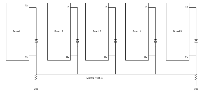
- pict1.png (4.8 KiB) Viewed 998 times
simonf Fri Sep 23, 2016 6:42 pm
Your welcome to the help. Glad you got it going its about the easiest and most flexible way to connect a bunch of uPs you can even get away with a mix of 3/5V devices.
RogerClark Fri Sep 23, 2016 8:37 pm
Joe
It looks like an ingeniously simple system.
Perhaps it needs a name 
“Maple bus”
joevpt Fri Sep 23, 2016 9:57 pm
Roger,
In order to use the Maple mini in my project (porting it directly from Arduino Mega), I would need the I2C library to support both master and slave mode. This solution is so much easier that trying to add the slave code to the library, and while it does mean I need to write a little more code to make a protocol as others have described in the topic, it adds the functionality without any limitations.
I like ‘Maple bus’ as a term, but of course the solution works with any MCU which has a UART port.
Great forum, with lots of great ideas here, so well done to you all.
Joe
RogerClark Fri Sep 23, 2016 10:08 pm
Hi Joe
Thanks
I understand that it will work with any MCU and you can have 5V and 3.3V on the bus at the same time, which is great as sometimes there is a need to mix 5V Arduino pro-mini’s and STM32 in the same project.
So “Maple bus” is perhaps not the best name, but I couldn’t think of anything else at the spur of the moment
Pito Sat Sep 24, 2016 6:20 am
It is basically an “1-Wire” bus developed by Dallas Semiconductor. I think to write a well working software “driver” for such a setup would be a challenge.
martinayotte Sat Sep 24, 2016 4:48 pm
Indeed, the challenge is the software, not the hardware, same challenge as with an RS485 bus : Collisions when used in Multi Master protocol.
Though, having a single Master/Arbiter solves such issues.
Pito Sun Sep 25, 2016 8:46 am
As I wrote earlier, I had a 1Master – XSlaves setup (a small lab automation project in 80ties) and we finished with an app where the Master sent a request with [addr] and [command] and the Slave_XY responded with some action or [data]. Afaik to make it work somehow reliably we put a long delays/timeouts everywhere to avoid collisions (the responses from the Slaves were not immediate sometimes, and depended on other external events)

But today are guys much clever than we were in the era of the dinosaurs
so I am quite confident a good sw for that 1-wire setup is doable..
douginarug Mon Mar 20, 2017 4:38 pm
Hello All,
I’m new to the STM32 devices and this forum.
I was wondering if anyone has been working on the “maple bus” code. Does anyone have some example code or possibly a new library for this type of communication?
I had a project that used two pro mini arduinos that talked I2C. One master and one slave. I was wanting to port that project to the maple mini, but don’t want to re-invent the wheel.
Sign in to reply
