MainPort USART
Pins 3 and 4 carry serial TX and RX in USART mode.

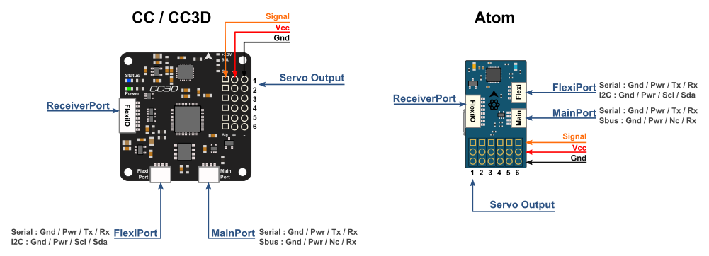
Original CopterControl 3D board connector reference for MainPort, FlexiPort, ReceiverPort, USB and six servo channels.
Signal contact for servo channel 2.
| Pin | Signal | Direction | Function |
|---|---|---|---|
| MAIN-1 | GND Return | Return | Connect to the board ground return. |
| MAIN-2 | RAW_VCC Unregulated rail | Unregulated rail | Tracks the voltage applied through the servo or receiver power rail. USB-only power does not energize the accessory rail. |
| MAIN-3 | MAIN_TX Output | Output | USART transmit output in serial mode. |
| MAIN-4 | MAIN_RX Input | Input | USART receive input in serial mode. Receiver protocols depend on firmware configuration. |
| FLEX-1 | GND Return | Return | Connect to the board ground return. |
| FLEX-2 | RAW_VCC Unregulated rail | Unregulated rail | Tracks the voltage applied through the servo or receiver power rail. USB-only power does not energize the accessory rail. |
| FLEX-3 | FLEX_TX_SCL Mode-dependent | Mode-dependent | USART transmit in serial mode, or I²C clock in I²C mode. |
| FLEX-4 | FLEX_RX_SDA Mode-dependent | Mode-dependent | USART receive in serial mode, or I²C data in I²C mode. |
| RC-1 | GND Return | Return | Connect to the board ground return. |
| RC-2 | RAW_VCC Unregulated rail | Unregulated rail | Tracks the voltage applied through the servo or receiver power rail. USB-only power does not energize the accessory rail. |
| RC-3 | RC_IO1 Mode-dependent | Mode-dependent | PWM input 1, or PPM input in the modes that select PPM on pin 3. |
| RC-4 | RC_IO2 Mode-dependent | Mode-dependent | PWM input 2 in the appropriate receiver modes. |
| RC-5 | RC_IO3 Mode-dependent | Mode-dependent | PWM input 3, or PWM output 7 in the documented output modes. |
| RC-6 | RC_IO4 Mode-dependent | Mode-dependent | PWM input 4, or PWM output 8 in the documented output modes. |
| RC-7 | RC_IO5 Mode-dependent | Mode-dependent | PWM input 5, or PWM output 9 in the documented output modes. |
| RC-8 | RC_IO6 Mode-dependent | Mode-dependent | PWM input 6, PWM output 10 or PPM input. Check the selected ReceiverPort mode. |
| USB-1 | VBUS Supply input | Supply input | 5 V USB supply contact. |
| USB-2 | USB_DM Bidirectional | Bidirectional | Negative USB differential data contact. |
| USB-3 | USB_DP Bidirectional | Bidirectional | Positive USB differential data contact. |
| USB-4 | USB_ID Unconnected | Unconnected | ID contact is unused for this device connection. |
| USB-5 | GND Return | Return | Connect to the board ground return. |
| OUT1-1 | GND Return | Return | Connect to the board ground return. |
| OUT1-2 | RAW_VCC Unregulated rail | Unregulated rail | Tracks the voltage applied through the servo or receiver power rail. USB-only power does not energize the accessory rail. |
| OUT1-3 | PWM_OUT1 PWM output | PWM output | Signal contact for servo channel 1. |
| OUT2-1 | GND Return | Return | Connect to the board ground return. |
| OUT2-2 | RAW_VCC Unregulated rail | Unregulated rail | Tracks the voltage applied through the servo or receiver power rail. USB-only power does not energize the accessory rail. |
| OUT2-3 | PWM_OUT2 PWM output | PWM output | Signal contact for servo channel 2. |
| OUT3-1 | GND Return | Return | Connect to the board ground return. |
| OUT3-2 | RAW_VCC Unregulated rail | Unregulated rail | Tracks the voltage applied through the servo or receiver power rail. USB-only power does not energize the accessory rail. |
| OUT3-3 | PWM_OUT3 PWM output | PWM output | Signal contact for servo channel 3. |
| OUT4-1 | GND Return | Return | Connect to the board ground return. |
| OUT4-2 | RAW_VCC Unregulated rail | Unregulated rail | Tracks the voltage applied through the servo or receiver power rail. USB-only power does not energize the accessory rail. |
| OUT4-3 | PWM_OUT4 PWM output | PWM output | Signal contact for servo channel 4. |
| OUT5-1 | GND Return | Return | Connect to the board ground return. |
| OUT5-2 | RAW_VCC Unregulated rail | Unregulated rail | Tracks the voltage applied through the servo or receiver power rail. USB-only power does not energize the accessory rail. |
| OUT5-3 | PWM_OUT5 PWM output | PWM output | Signal contact for servo channel 5. |
| OUT6-1 | GND Return | Return | Connect to the board ground return. |
| OUT6-2 | RAW_VCC Unregulated rail | Unregulated rail | Tracks the voltage applied through the servo or receiver power rail. USB-only power does not energize the accessory rail. |
| OUT6-3 | PWM_OUT6 PWM output | PWM output | Signal contact for servo channel 6. |
Pins 3 and 4 carry serial TX and RX in USART mode.
Pin 3 is TX or SCL. Pin 4 is RX or SDA. Select the protocol in the firmware configuration.
ReceiverPort assignments change with the firmware mode. OpenPilot documents PWM inputs, PPM on pin 3 or pin 8, and PWM outputs 7–10.
Use a standard data cable with a USB host for USB configuration.
| Parameter | Limit | Conditions and source |
|---|---|---|
| External supply rail4.8–15 V | 4.8–15 V | The external rail is passed to the peripheral power contacts without regulation. Use USB alone for the bench examples. OpenPilot CC3D Hardware Setup · Ports and pin-outs |
| Serial logic for this fixture3.3 V | 3.3 V | Use 3.3 V logic and a common return. Leave the accessory power pin isolated. OpenPilot CC3D Hardware Setup · Ports and pin-outs |
| USB power5 V from host | 5 V from host | Powers the board for configuration. The accessory rail remains off with USB as the only supply. OpenPilot CC3D Hardware Setup · Ports and pin-outs |
Matches the CopterControl 3D open hardware files. Match the key and PCB labels on your board before connecting a harness.