Spark Logic

DLO-138 OScope

willfly1 Sun Feb 26, 2017 5:38 pm

DSO-138 Oscope firmware

DLO-138 is alternate firmware for DSO-138 and adds second analog channel, two logic channels, more sample depth and serial port data output.

Code: https://github.com/ardyesp/DLO-138

pic3.png
pic3.png (153.54 KiB) Viewed 8814 times

Replies

mausi_mick Sat Nov 04, 2017 5:13 pm

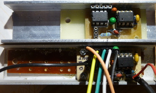
I have the preamps modified, here a picture:
DLO138_ILI9341_SPI_Preamps_with_TL072_and_MCP6S91.JPG
DLO138_ILI9341_SPI_Preamps_with_TL072_and_MCP6S91.JPG (44.07 KiB) Viewed 1276 times

mausi_mick Tue Nov 07, 2017 7:02 pm

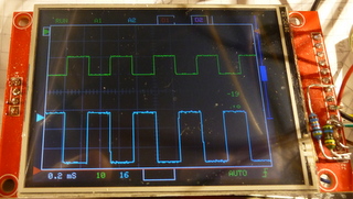
now the second preamp is nearly ready, I changed the TL072 in the first stage with the MCP6022 (R.R) because supply-voltage is only 5V.
The noise is from not perfect shielding . ?
DLO138_ILI9341_SPI_DualPreamp_MCP6022_MCP6S91.JPG
DLO138_ILI9341_SPI_DualPreamp_MCP6022_MCP6S91.JPG (45.75 KiB) Viewed 1238 times

mausi_mick Sat Nov 11, 2017 2:16 am

Now I have made a new pcb for the maple-mini in the same size with the 2.8″ display includes 5V supply and the MCP4822 DAC.

It is nearly ok, butI have eliminate the DAC beacause I have to change it from 3.3V to 5V like the other devices (PGA’s) on SPI-2.

And I have to make something with the trigger …

A new video: https://youtu.be/3KJTmGfGuTA

rexnanet Sat Nov 11, 2017 8:35 am

Nice work!
3.3V to 5V: why are you mentioning SPI? 3.3V SPI should work with 5V slave if you ignore MISO line.
MCP6022 doesn’t have a great BW but should be enough.
Is your trigger done in SW? If so it should be easy.

mausi_mick Sat Nov 11, 2017 11:08 am

hi rexnanet,
the problem is solved,
It was a “design” error on the pcb-layout, I connected CS to CLK, MOSI to CS and CLK to MOSI of the MCP4822.
Now all is ok and the offset for both channels works. And the encoders work smooth and soft.

Thanks !

mausi_mick Wed Nov 15, 2017 2:50 pm

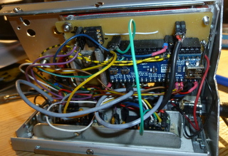
Now I have finished the most of the HW and fixed it on the front-panel.

The supply m( USB or 7,5V-12V DC) is on the left side. BTN4 and Reset-Button are on the right above the two encoders.

DLO138_ILI9341_SPI_backside.JPG
DLO138_ILI9341_SPI_backside.JPG (61.74 KiB) Viewed 1155 times

rexnanet Wed Dec 13, 2017 3:21 pm

[mausi_mick – Mon Nov 20, 2017 4:17 pm] –
Now I have tested an quadencoder on an Namiki motor, the phase difference is 90° :lol:

https://www.youtube.com/watch?v=GXj4ve7 … e=youtu.be

Nive work :)

I’ve got some DSO150 to try them out. It works great but only one channel is not very nice :)
I’m thinking about making a similar approach but using the F303 and getting to 10MSPS/channel.
I’m going to try changing the F103 for the F303 on a bluepill to test it (like ThunderOwl did :) ).
Maybe it could be possible to use this code with that chip…

dev Thu Feb 08, 2018 3:05 pm

Hi mausi_mick,
Could you please share the updated schematic for dso?
I want to give a try on this.

mausi_mick Thu Mar 08, 2018 2:45 am

Hi,

here the code,
I used Arduino IDE 1.8.4

(25.16 KiB) Downloaded 208 times

sslobodyan Thu Mar 08, 2018 6:49 pm

mausi_mick, can you show your schematic and pcb?

mausi_mick Fri Mar 09, 2018 3:47 am

eagle files or so are not existing,

The pcb is hand – made with a small carpet knife.

dev Sun Mar 25, 2018 4:02 am

Could you please share the rough schematic. I saw there were changes discuss in thread. So not much sure about schematic to follow.

mausi_mick Wed Mar 28, 2018 12:51 pm

Hi, long time …

I realized the two pre-amplifiers with 2 MCP6S91 PGA’s similar like this schematic:

https://jasmedia2011.files.wordpress.co … 472321.png

The used pins of the maple-mini you can see in “global.h” of the last zip-file DLO-138-MaMi_05.

I used 2 spi,
the first for the display ILI9341,
the second spi for the PGA’s / MCP6S91 and the DAC’s MCP4822 .

Not solved is the triggering.

Col68 Sun Apr 08, 2018 11:37 am

Hello Willfly1,

thank you for this beautiful sharing, a perfect device, even if i can not do it because it is too complex for an amateur like me, maybe in the future … great respect for you and thank you again for sharing, cordially

dave j Thu Apr 12, 2018 7:19 pm

[mausi_mick – Wed Mar 28, 2018 12:51 pm] –
Not solved is the triggering.

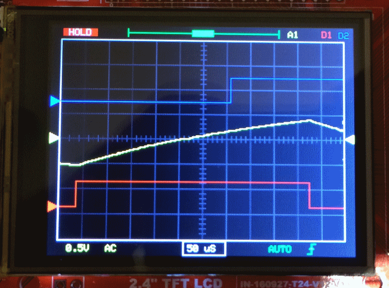
A really cheap way of doing triggering is to use the ADC’s analog watchdog.

For a rising trigger set the low threshold (LTR) to zero and the high threshold (HTR) to the value you want to trigger on (for a falling trigger, set HTR to 4095 and LTR to the trigger value). You can check the AWD flag in the ADC status register (which your code already loads when checking if a conversion is complete) to see if a trigger has occurred. You can even get it to generate an interrupt if you decide to change to capturing samples using DMA in the future.

Keep in mind you’ll have to scale the trigger level you program the AWD registers with to match your OPAMP gain.

It might be worth worth considering moving to a DMA in any case. It actually makes things easier and you’ll be able to avoid the need to write assembler code. Let me know if you want to know how I go about it for my F3 based oscilloscope project.

rexnanet Mon Apr 16, 2018 5:32 pm

Hi dave j,

Are you using this code on a F303?
Do you have arduino ide working on the F303?
I was trying to get a base code working with STM32 HAL but it’s still in it’s early days. I have managed to get ILI9341 working but still haven’t digged into the ADC stuff. On arduino would be a lot easier…

dave j Tue Apr 17, 2018 12:31 pm

[rexnanet – Mon Apr 16, 2018 5:32 pm] –
Hi dave j,

Are you using this code on a F303?

No, I’m developing something from scratch.
Do you have arduino ide working on the F303?
No. I’m using Qt Creator as a development environment and targetting the STM32 LL libraries (rather than the HAL ones which reportedly are a bit buggy). Qt Creator is a better C/C++ IDE than Eclipse and you can get it to deploy code to the device and remotely debug too.
I was trying to get a base code working with STM32 HAL but it’s still in it’s early days. I have managed to get ILI9341 working but still haven’t digged into the ADC stuff.
STM32Cube has some good example code that helped me figure out how to do things. Some MCUs have more/better examples than others – don’t just look at those for the MCU you’re targeting.
On arduino would be a lot easier…
Sadly, I think with libraries it’s a case of simple enough for beginners to understand or flexible enough to do complex things. At least with arduino you can ignore its libraries and use others/code direct to the hardware.

Let me know if you want me to describe the approach I’m taking to capturing and triggering.

arpruss Wed May 16, 2018 5:28 pm

[rexnanet – Mon Apr 16, 2018 5:32 pm] –
Are you using this code on a F303?
Do you have arduino ide working on the F303?
I was trying to get a base code working with STM32 HAL but it’s still in it’s early days. I have managed to get ILI9341 working but still haven’t digged into the ADC stuff. On arduino would be a lot easier…

I want to make an F303-based oscilloscope, too. I am thinking: two channels, 10M samples/sec (by DMA and interleaving). So far I have an F303 board (by replacing the F103 on a “blue” pill with an F303) and a working stm32generic Arduino core fork.

I am wondering if I should start from scratch or with the DLO-138 source code.

Another possibility would be to buy a DSO-138, transplant an F303 to it (hopefully without breaking anything), and then work on the software.

Any thoughts?

rexnanet Thu May 17, 2018 1:28 pm

My plans are the same :)

I’m thinking on using the DLO-138 as a starting point and if it’s not viable then try to use STM32-HAL or something. But using DLO-138 would give a nice head start and having a “working” arduino core makes it even more simple :)

I’ve also swapped the F103 for an F303 on a blue pill. Swapping it on a DSO-138 or even on a DSO-150, as I’ve thought, it’s no good because of the single analog channel.
I’m thinking about making myself a pcb to get everything together.

Sign in to reply