DLO-138 OScope
willfly1
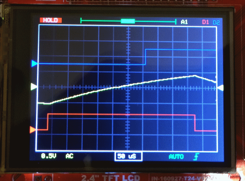
DLO-138 is alternate firmware for DSO-138 and adds second analog channel, two logic channels, more sample depth and serial port data output.
Code: https://github.com/ardyesp/DLO-138

- pic3.png (153.54 KiB) Viewed 8814 times
willfly1
DLO-138 is alternate firmware for DSO-138 and adds second analog channel, two logic channels, more sample depth and serial port data output.
Code: https://github.com/ardyesp/DLO-138

ahull Thu May 17, 2018 2:19 pm
dave j Fri May 18, 2018 1:37 pm
[rexnanet – Thu May 17, 2018 1:28 pm] –
My plans are the same![]()
I’m thinking on using the DLO-138 as a starting point and if it’s not viable then try to use STM32-HAL or something. But using DLO-138 would give a nice head start and having a “working” arduino core makes it even more simple
I guess it comes down to how different do you want your scope’s UI to be from that provided by DLO-138.
I’ve also swapped the F103 for an F303 on a blue pill. Swapping it on a DSO-138 or even on a DSO-150, as I’ve thought, it’s no good because of the single analog channel.
I’m thinking about making myself a pcb to get everything together.
How many of the other F303 peripherals, e.g. built in OPAMPs and comparators, do you envisage using? That could drastically affect which pins you can use for things like screens, buttons, etc.
I found STM32CubeMX is a good way of trying different combinations of peripheral and pin assignments with it warning you of incompatible combinations.
arpruss Fri May 18, 2018 6:25 pm
RogerClark Fri May 18, 2018 11:58 pm
[arpruss – Fri May 18, 2018 6:25 pm] –
I’m thinking of using my phone for a screen, at least for initial testing, which will save some pins. An advantage is that the phone can also power the board. I’m currently writing an Android app that functions as a vector display for an Arduino sketch, via USB serial.
Interesting..
Did you write the App?
I found that Android didn’t recognise the VID PID of leadlabs CDCACM , last time I tried it . ( but that was years ago, so things may have changed)
arpruss Sat May 19, 2018 3:32 am
[RogerClark – Fri May 18, 2018 11:58 pm] –
Interesting..Did you write the App?
It’s in progress here: https://github.com/arpruss/vectordisplay (see the VectorDisplay example; the library I’m using for serial comm isn’t mine).
It seems to work fine with the product and vendor id that STM32GENERIC uses by default. I haven’t tried it with the LeafLabs one.
I found that Android didn’t recognise the VID PID of leadlabs CDCACM , last time I tried it . ( but that was years ago, so things may have changed)
I found that some Android serial libraries didn’t recognize the device, but the one I ended up using recognizes it just fine.
RogerClark Sat May 19, 2018 7:21 am
arpruss Sun May 20, 2018 3:52 am
The tentative Arduino side is here: http://github.com/arpruss/vectordisplayarduino , but I expect the API will change.
RogerClark Sun May 20, 2018 10:26 am
rtek Fri Jul 20, 2018 3:35 am
I’m trying to use a mcufriend display (which works fine on Arduino Mega2560 and returns the ID code 0x154),
But even without the display, when I look at the state of the pin with an LED and an oscilloscope, I noticed that the PB3 bit is floating.
The strange thing is that the original firmware of the DSO150 does not leave the PB3 pin floating, the LED can light (and blink) and the oscilloscope shows pulses.
What could be happening?
I have 2 bluepill, and both show the PB3 pin floating.
rtek Fri Jul 20, 2018 5:11 pm
I had to disable the JTAG of this PB3 pin:
I added the instruction below at the beginning of the subroutine “setup”
afio_cfg_debug_ports(AFIO_DEBUG_NONE);
rtek Fri Jul 20, 2018 9:08 pm
With the help of Sr. David (from https://github.com/prenticedavid) I was able to modify the Adafruit_TFTLCD_8bit_STM32 library for MCUFRIEND_kbv.
The code has been stored here (because this site – stm32duino – does not allow the file size):
https://github.com/ardyesp/DLO-138/issues/10
P.S.: The mcufriend library supports many display models, it may be cool to use this library instead of others, since the support is exceptional!
10. It currently supports UNO shields with "mcufriend.com" pcbs with controllers:
HX8347-A 240x320 ID=0x8347 #define SUPPORT_8347A *** Untested ***
HX8347-D 240x320 ID=0x4747 #define SUPPORT_8347D
HX8347-G 240x320 ID=0x7575 #define SUPPORT_8347D
HX8347-I 240x320 ID=0x9595 #define SUPPORT_8347D
HX8352-A 240x400 ID=0x5252 #define SUPPORT_8352A
HX8352-B 240x400 ID=0x0065 #define SUPPORT_8352B
HX8357-B 320x480 ID=0x8357 (shares init with 8357-D)
HX8357-C 320x480 ID=0x9090 (ID has changed from 0x8357)
HX8357-D 320x480 ID=0x0099 #define SUPPORT_8357D_GAMMA
HX8367-A 240x320 ID=0x6767 #define SUPPORT_8347D
ILI9225 176x220 ID=0x9225 #define SUPPORT_9225
ILI9226 176x220 ID=0x9226 #define SUPPORT_9225
ILI9302 240x320 ID=0x9302
ILI9320 240x320 ID=0x9320
ILI9325 240x320 ID=0x9325
ILI9326 240x400 ID=0x9326 #define SUPPORT_9326_5420
ILI9327 240x400 ID=0x9327
ILI9328 240x320 ID=0x9328
ILI9329 240x320 ID=0x9329
ILI9331 240x320 ID=0x9331
ILI9335 240x320 ID=0x9335
ILI9338 240x320 ID=0x9338
ILI9340 240x320 ID=0x9340
ILI9341 240x320 ID=0x9341
ILI9342 320x240 ID=0x9342 #define SUPPORT_9342
ILI9481 320x480 ID=0x9481
ILI9486 320x480 ID=0x9486
ILI9487 320x480 ID=0x9487
ILI9488 320x480 ID=0x9488 (weird 555 display :#define SUPPORT_9488_555)
LGDP4532 240x320 ID=0x4532 #define SUPPORT_4532
LGDP4535 240x320 ID=0x4535 #define SUPPORT_4535
NT35310 320x480 ID=0x5310 (hardware must be set for 8-bit parallel)
R61505 240x320 ID=0x1505 works like an ILI9320
R61505V 240x320 ID=0xB505
R61505W 240x320 ID=0xC505
R61509V 240x400 ID=0xB509 #define SUPPORT_B509_7793
R61520 240x320 ID=0x1520 (no Vertical Scroll)
R61526A 240x320 ID=0x1526 (no Vertical Scroll) configure NVM with sketch
R61580 240x320 ID=0x1580 #define SUPPORT_1580 *** Untested ***
R61581 320x480 ID=0x1581
RM68090 240x320 ID=0x6809
RM68140 320x480 ID=0x6814 #define SUPPORT_68140
S6D0139 240x320 ID=0x0139 #define SUPPORT_0139 (no Band Scroll)
S6D0154 240x320 ID=0x0154 #define SUPPORT_0154
SPFD5408 240x320 ID=0x5408
SPFD5420 240x400 ID=0x5420 #define SUPPORT_9326_5420
SSD1963 800x480 ID=0x1963
SSD1289 240x320 ID=0x1289 #define SUPPORT_1289
ST7781 240x320 ID=0x7783 #define SUPPORT_7781 (no Vertical Scroll)
ST7789V 240x320 ID=0x7789
ST7793 240x400 ID=0x7793 #define SUPPORT_B509_7793
ST7796 320x480 ID=0x7796
UC8230 240x320 ID=0x8230 #define SUPPORT_8230
UNKNOWN 320x480 ID=0x1511 (scroll directions not correct)
UNKNOWN 240x320 ID=0x1602
UNKNOWN 240x320 ID=0xAC11
UNKNOWN 240x320 ID=0x2053 weird controller from BangGood (was ID=0x0000)
UNKNOWN 240x320 ID=0x8031 (no Vertical Scroll)
Fuintur Wed Dec 19, 2018 1:46 am
I’ve been trying to assemble this oscilloscope. I’m particularly interested in the second channel addition, so I’m going through the whole hardware modification. I had an old DSO138 I burned laying around, so I reused the usable components and designed a pcb focusing on making it easy to make at home. I tried to get all the hardware in one pcb where I can kind of plug the DSO138 on top as kind of a shield (with some modifications I haven’t made yet). The pin locations and basically every connection there is between the usual DSO and the new DLO maps from my shield into the DSO, leaving the taller components or those that need to stay accesible (switches, encoder…) out of the DSO outline. I’m not sure all these single pin connections are going to be possible to make in a “shield” kind of setting, but I’m trying. It’s still untested so use at your own risk.
I would have branched/forked/pulled this into the ardyesp github, but I have no idea how to use github and I haven’t had the time to learn, but here you have the eagle files: https://github.com/Damrod/DLO-board
There’s anyhow something I’m struggling to understand from the schematics, so I don’t think I can properly render it in my pcb: the “D CH1” “D CH2″… do they map into some connection os is it just informational? Is it like the encoder label that maps the way I mapped it or…? I attached an image to indicate this question.